Terrain
 left click
Terrains are topographic meshes created by lifting a surface from 3D curves, contour lines, point clouds or meshes.
- Insert a terrain
- Control points
- Elevation Data
- Insert options and parameters
- Edit options
- Graphical display
Insert a terrain
After running the laTerrain command, the Terrain insert dialog box will appear. This dialog displays the basic options for the Terrain object, divided into three tabs:
- Terrain: terrain parameters.
- Contour lines: display settings for contour lines on the terrain.
- Material: material settings for the terrain object.
Steps:
- Select the terrain Input data, which can be meshes, curves, or points.
- Set the terrain insert parameters and click OK to end the command.
- The terrain object will be now generated in the model.
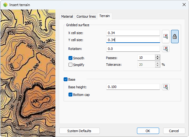
Insert dialog box for the Terrain object
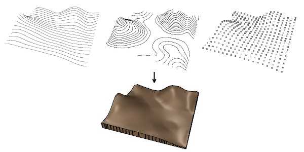
Terrains can be generated from different types of input data
Control points
Terrains have the same control points as the curves used to generate them (Elevation data), and the curves used for terrain operations ( such as Terrain Add Hole, Terrain Add Cut and Fill, etc.). A move control arrow will appear next to each curve, allowing you to move the entire curve.
Control points are integrated with the terrain and automatically enabled when selecting terrains individually, provided the total number of control points does not exceed 100.
Control points can be disabled in the Elevation data tab,in the Properties area of the Edit panel, after selecting the Elevation data from the selection list.
Control points on terrains
Elevation data
The input data of the terrain is displayed listed under the Elevation Data node in the Selection List of the Edit Panel, as long as the terrain is selected.
Each of the inputs (lines or points) can be individually selected, edited, or removed from the list, and the terrain will be recalculated.
Options and parameters
The terrain insert options and parameters are divided into different tabs, accessible from the following dialogs:
- Insert dialog box (only available when inserting new terrains).
- Properties area in Edit Panel.
- Object Properties dialog.
- Properties Explorer dialog.
General
General attributes for the Terrain object.
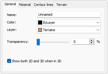
General tab in Properties area.
- Name
Rename the terrain object. - Color
Defines the color for the terrain in non-realistic display modes. It can inherit from its layer, block, or be custom-set. - Layer
Set the layer where the terrain object is located. - Transparency
Set the transparency level for the object in 3D display mode. - Show both 2D and 3D when in 3D
Displays contour lines on the terrain when it’s in 3D mode.
Terrain
Lands Design uses the Delaunay triangulation method to generate terrains, a popular algorithm that optimizes triangulation using points with known elevation values.
Terrains can be created directly from triangulation faces or by adjusting a grid to the shape obtained after triangulation, producing a smooth surface.
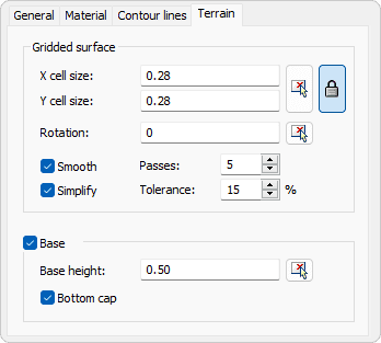
Terrain tab in Properties area.
- Gridded surface
When this option is enabled, you can control the following parameters: - Cell size
- Rotation
- Smooth
- Simplify
- Use the grid model to model holes and cut and fills
- Base height
Defines the thickness of the terrain base, based on the lowest elevation data. If unchecked, the terrain is generated as an open mesh.
Contour lines
Contour lines are 2D display elements that represent the terrain's topography, illustrating relief and altitude variation. The default contour interval is calculated based on elevation ranges but can be edited.
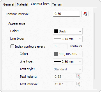
Contour lines tab in Properties area.
- Contour interval
Sets the distance between consecutive contour lines. - Appearance
Customizes 2D display settings for terrain contour curves. You can define indexed contours, add text labels, and assign different line properties.
Material
This tab lets you change the textured image assigned to this element and define the image size, reflectivity and transparency.
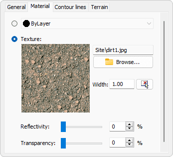
Material tab in Properties area.
Elevation data
The Elevation data parameters can be edited from the Elevation data tab in the Properties area of the Edit panel, once selected the node or one of the listed inputs.
For the Elevation data to appear in the selection list, the terrain must first be selected from the viewport.
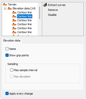
Elevation data tab in Properties area.
- Name
Rename the input. - Show grip points
Enable or disable the control points for the input data. - Sampling
Controls how data points are selected or extracted from the inputs to define the terrain. It influences the accuracy and spacing of the points used in the triangulation process but doesn't directly affect the overall detail of the resulting mesh. - Max sample interval
Define the maximum distance between sampled points along the input curve. A smaller interval increases accuracy but may create a more complex terrain mesh. - Max deviation
Specifies the maximum allowed deviation between the input curve and the simplified version used for terrain generation. Lower values preserve more detail, while higher values allow more simplification.
Edit options
These are the edit options for the Terrain object, available in the Edit area of the Edit panel:
 Update
- Copy properties from another object
 Extract curves
- Adjust
- Terrain
 Pick boundary
 Remove boundary.(This command only appears when a new boundary has been added to the terrain)
 Add inner boundary
 Add contour curve
 Add hole
 Add cut and fill
 Add path
 Divide
 Volume of earthmoving
- Extract elevation data triangulation.
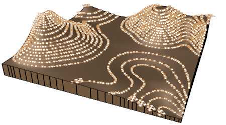
Terrain graphical display
Lands Design offers different simultaneous 2D and 3D displays for terrains in the model. The number of contour lines in the 2D display is determined by the Contour lines settings.
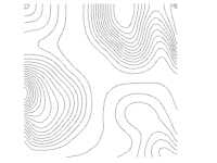
|
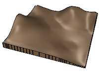
|
| Terrain 2D display | Terrain 3D display |