Terrain Add Path
 left click
This command modifies the terrain geometry to place a path, adjusting the terrain’s elevation based on a defined path curve. The process is commonly used for creating roads, walkways, or similar structures. The terrain is reshaped by adding or removing soil to fit the path according to the specified slope and width.
This operation also adds a division to the terrain using the same path curve and the path width, as if you were using the laTerrainDivide command.
Add Path
Steps:
- Pick a terrain. Press Enter or right-click when done.
- Specify the path width.
- Specify the angle for the slope within the interval (0 to 90).
- Select a curve to define the path itinerary.
- The terrain will add and remove the soil volume required to match with the curve position, according to the given slope angle.

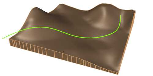
Terrain before the add path operation

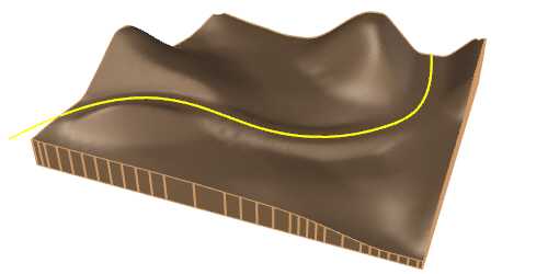
Terrain after the add path operation
Control points
The control points of the terrain path allow you to modify the path elevation and itinerary. They are the same as those of the curve used for this operation. In addition, there is a move control arrow to reposition the entire hole operation.
These control points are integrated with the terrain and are visible when the terrain's control points are enabled.
Control points can be disabled in the Earthmoving tab, in the Properties area of the Edit panel, after selecting the path from the selection list.
NoteThe control points of the subdivision created by a path depend on the terrain path control points, regardless whether they are enabled or not in the subdivision settings.
Options and Parameters
The Path parameters are the same as those for the Cut and Fill operation, in addition to the specific Path tab. They can be edited from the Properties area of the Edit panel, once selected under the Earthmoving operations list.
For the Earthmoving operations to appear in the selection list, the terrain must first be selected from the viewport.
Path

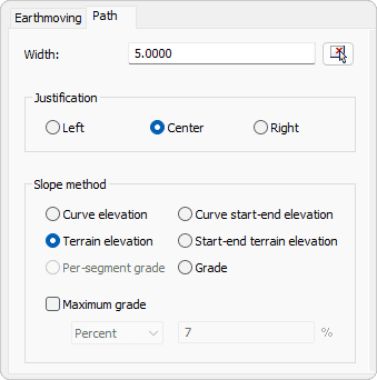
Path tab in Properties area.
- Width
Defines the width of the path. - Justification
specifies how the path width is aligned in relation to the path curve. It can be centered, left-aligned, or right-aligned. - Slope method
- Curve elevation
Adjust the path elevation to match the elevation of the curve - Terrain elevation
Adjust the path to the current elevation of the terrain along the curve. - Curve start-end elevation
Match the path elevation with the curve elevation at its start and end points. - Start-end terrain elevation
Match the path elevation with the terrain elevation at the start and end points of the curve. - Grade
Adjust the path elevation based on a specific grade. When this method is selected, the Grade tab is enabled for this operation. - Per-segment grade
Adjust the grade for each curve segment. When this method is selected, the Path command is subdivided into segments in the selection list, and the Grade tab is enabled for each of them.
- Curve elevation
- Maximum grade
This parameter ensures that the elevation changes do not exceed a specified degree of incline.
Grade

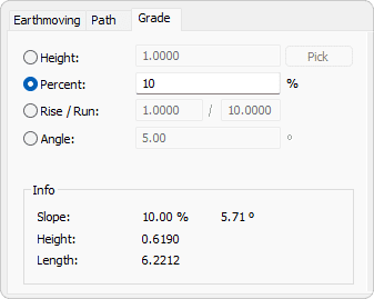
Grade tab in Properties area.
- Grade
- Height
Set the vertical elevation change of the path in model units.
This value indicates how much higher or lower the path will be relative to the base elevation. - Percent
Set the grade of the path expressed as a percentage.
This is calculated by dividing the rise by the run and multiplying by 100. For example, a 10% grade indicates a 10-unit rise for every 100 units of horizontal distance. - Rise/Run
Set the grade of the path expressed as a ratio of rise to run.
A 1:10 slope means that for every 1 unit of vertical rise, there is 10 units of horizontal run. - Angle
Set the grade of the path expressed in degrees.
This value represents the angle formed between the horizontal plane and the path.
- Height
- Info
Display the various measurements of the created terrain.
The edit options and parameters of the terrain subdivision generated by this command are the same as those generated with the laTerrainDivide command.
Edit options
These are the edit options for the Path operation, available in the Edit area of the Edit panel:
