Ramp
 left click
Ramps are used to provide accessible and gradual elevation changes.
Insert a ramp
After running the laRamp command, the Ramp insert dialog box will appear. This dialog shows the basic options of the Ramp object in different tabs.
- Ramp: ramp parameters.
- Flight: ramp flight parameters.
- Arrow: arrow parameters.
- Material: material settings for the Ramp object.
Steps:
- Select the Ramp parameters. Click OK to close the dialog
- Pick an existing open curve in the model to define the ramp path, or select a different option in the command line.
- Polyline: the ramp will be created as if you were drawing a polyline.
- Spline: the ramp will be created as if you were drawing a spline.
- Arc: the ramp will be created as if you were drawing an arc. The first click determines the insert point. Second click determines a middle point in the arc. The third and last click determines where the arc ends.
- Press ENTER, ESC or right-click to end the command.
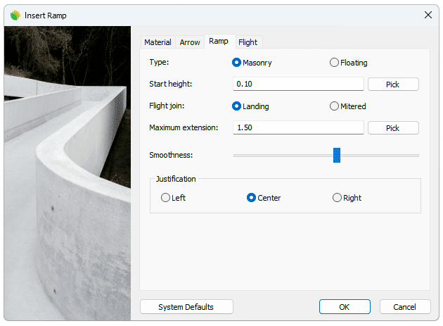
Insert dialog box for the Ramp object
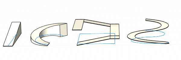
Ramp examples created from different types of curves
Control points 
Ramp objects have the same control points as the curves used to generate them.
In addition, they have a Move control arrow, to move the whole object.
Ramp control points are automatically enabled when selecting ramps one by one. To turn one ore more Ramp object control points on just select the ramps and run the PointsOn command (or press F10). To turn a Ramp object points off, press the Esc button or run the PointsOff command.
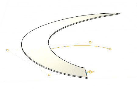
Control points on Ramp objects
Options and parameters
The Ramp object insert options and parameters are divided in different tabs, and are available from different dialogs:
- Ramp insert dialog box (only available when inserting new ramps).
- Ramp properties area in Edit Panel.
- Object Properties dialog.
- Properties Explorer dialog.
General
General attributes for the Ramp object: Name, Color and Layer.
Ramp
- Type: Select the ramp construction method by choosing between:
- Masonry: Ramp built on a solid structure.
- Start height: Set the initial elevation at the beginning of the ramp.
- Floating: Cantilever-built ramp.
- Thickness: Set a constant thickness along path for the floating ramp.
- Flight join: (Only enabled from the insert dialog.) Specify how the joint behaves during changes of slope direction on ramps created from polylines or rectangles.
- Landing: Create a flat platform with no slope at the intersection points of the ramp.
- Maximum extension: maximum length for landings.
- Mitered: Create miter joints at the intersection points of the ramp.
- Smoothness: Precision in which the object is subdivided along the axis curve in order to fit with its path. This parameter is only relevant when the Ramp object has been created from curved curves.
- Justification: Set the position of the axis relative to the structure. There are three possible justifications:
- Left: The path curve remains on the left of the ramp.
- Middle: The ramp will be built by distributing half of its thickness on either side of the path curve.
- Right: The path curve remains on the right of the ramp.
Flight
- Start width: Width at the starting point.
- End width: Width at the ending point.
- Slope
- Height: Ramp height in model units.
- Percent: Incline measurement in percentage.
- Rise/ Run: Slope expressed as a ratio (For example, a 1:12 slope means that for every 1 unit of vertical rise, there is 12 units of horizontal run.)
- Info
Notes
For a ramp created from a polyline, you can edit the slope of each segment individually. To do so, select each Flight from the selection list after selecting the ramp.
Arrow
- Arrow:
- Color: set the color style for the slope arrow.
- Label: Label options for the slope arrow.
Material
This tab lets you change the textured image assigned to this element and define the image size, reflectivity and transparency.
Edit options
These are the edit options for the ramp object, available in the Edit area of the Edit panel:
 Update
- Copy properties from another object
- Copy to another curve
- Invert curve
 Extract curves
- Adjust
- Don't adjust to terrain
Ramp graphical display
The Ramp object offers a simultaneous 2D and 3D display on the drawing.
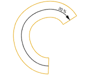
|
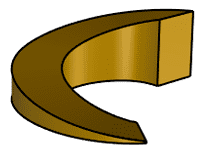
|
| 2D | 3D |