Viewport
The Viewports are windows in the graphics area that display views of your model and allow interaction with it.
Each viewport, can set a view with a distinct orientation of the model, as well as a different display mode.
1. Model Viewport elements
Viewport title
Each viewport has a viewport title on the upper-left corner.
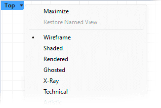
- Right-click on the viewport title or click the triangle button to show the menu for view management commands. Most of the commands can be found on the Visualization Toolbar.
- Click the title of a viewport to activate the viewport without deselecting objects. The active viewport highlights its title in blue.
- Double-click a viewport title to maximize the viewport, or restore the multi-viewport layout.
- Drag a viewport title to move the viewport around.
Note: To restore the default four-viewport workspace, use the 4View command from the Visualization toolbar.
Construction plane grid
The grid is a visual reference system that consists of a series of intersecting horizontal and vertical lines forming a grid pattern. This grid is associated with the Construction plane and serves as a visual aid to help users dimension and orient objects in the 3D space within Rhino.
World axis icon
The World Axis icon in a 3D workspace serves as a visual reference for the global orientation within the three-dimensional coordinate system. It typically consists of three arrows representing the X, Y, and Z axes, each assigned a specific color (red for X, green for Y, and blue for Z). This icon aids in understanding the navigation and orientation of objects within the 3D environment.

Note: The visibility of the background, Grid and Axis can be controled through the Display Panel.
2. Viewport tabs
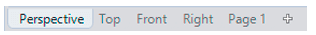
Viewport tabs are located at the bottom of the main viewport frame by default. Each model and layout viewport has a tab. The tabs are useful for managing multiple-page layout style viewports along with standard modeling viewports.
Two types of viewports provide different functions:
In model viewports, create your surface or solid model using the appropriate units and precision. They appear by default with the name of the corresponding view on the tabs (Perspective, Top, Front...).
In layout viewports, place one or more details of your model and add information that annotates the printed sheet, such as lists, bill of materials, general notes, title blocks, seals, and scale bars. They appear by default as numbered pages on the tabs (Page 1).
Click the  tab for options:
- Create New Layout viewport
- Import layout files
- New floating Viewport
- Split Horizontal
- Split Vertical
3. Viewport mouse navigation
| Navigation | |
|---|---|
 |
Activate a viewport
|
 |
Move and rotate
|
| Shift + |
Move and rotate
|
| Ctrl + |
Zoom
|
Several navigation commands feature their own graphical icons on the Standard bar
| Select objects | |
|---|---|
|
Select
|
| Shift + |
Add to selection
|
| Ctrl + |
Remove from selection
|
To select elements of a specific type, you can use the commands in the Selection toolbar
| Run commands | |
|---|---|
|
Initiate commands
|
|
Accept and deny command-line inputs
|